|
Have you ever been playing an N64 game, and, in the heat of action, the game has a bout of slowdown? If this has happened to you, take comfort in knowing we have all run into this problem many times in various N64 games. Back when the N64 was sold at retail, there wasn't much we could do, for knowledge of the N64 hardware was very limited. In recent years, people have discovered a solution to the slowdown problem. All it takes is a couple switches and some wires. This guide will walk you through the steps needed to Overclock Your N64.
Stuff You'll Need
First, this is a list of parts and tools you'll be needing:
- An N64 control deck
- One (1) 4.5mm security bit
- A phillips (four point star shape) screwdriver set with small sizes
- A roll of electrical tape
- A multimeter, to check for continuity and bridging
- A soldering iron (15 - 30w)
- rosin core solder and maybe some stand-alone flux
- A desoldering pump or desoldering braid, in case you use too much solder
- A box cutter/exacto-knife, or something thin enough to wedge behind/under the chip legs
- A dremel or drill, to make the holes in the N64 shell for the switches
- Two (2) panel mount SPST switches (single pole single throw, or 3 contacts and 2 switch positions)
- Six (6) pieces of thin (28 - 32AWG) insulated wire, length depends on your switch locations
- A multi-compartment container for all the screws, it helps you to remember where they all go
Theory
NOTE: All pictures can be clicked on to be viewed at full size.
Next, before the actual guide, I feel we should discuss the theory behind this mod, so you have a decent understanding of what is going on.
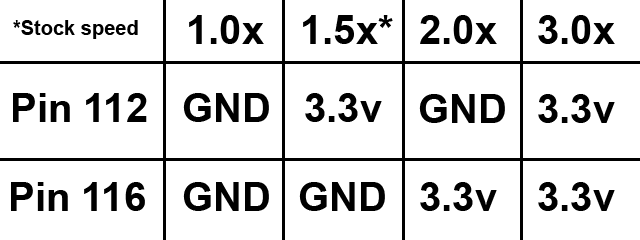
There are two pins (or legs) on the N64's CPU. These can be set to high (3.3v) or low (ground), which in turn sets the multiplier for the CPU's clock signal, which is based on the clock speed of the RCP (Reality Co-Processor). The chart below explains the multipliers.
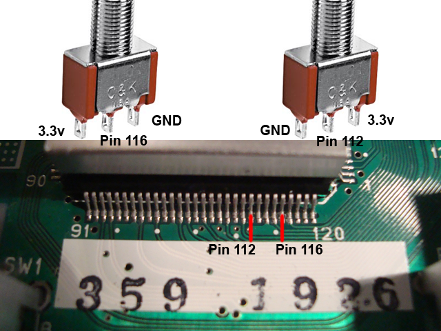
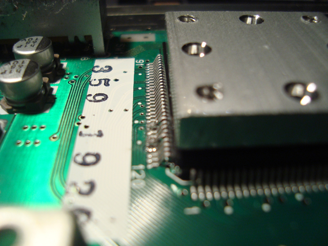
And here is a picture showing the two pins on the actual CPU you need to work with, along with an example switch diagram.
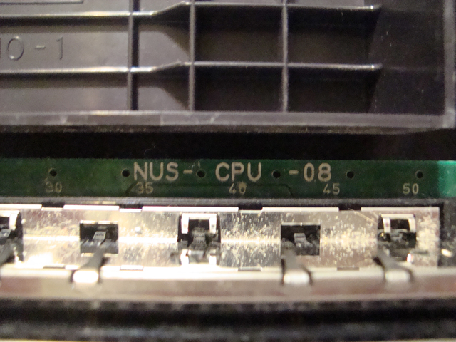
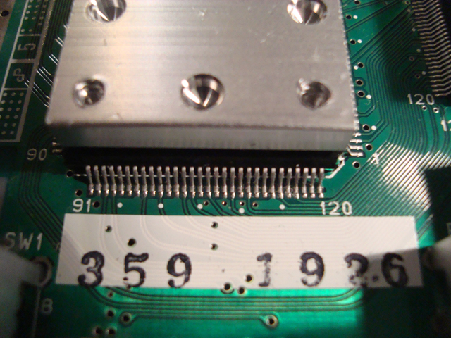
The revision of your N64's motherboard is a crucial aspect of the overclock mod as well. Most people agree that older revisions are unstable when overclocked and crash frequently, so what you want is a high revision N64. The one used in this guide is a NUS-CPU-08, which is the second last major revision of the N64.
Instructions
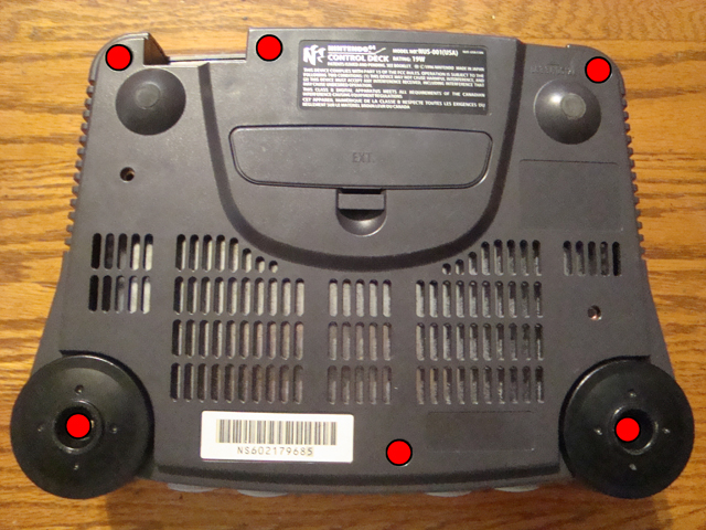
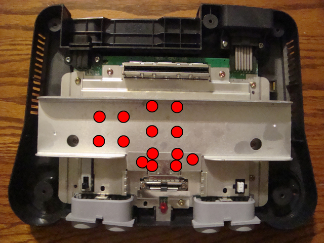
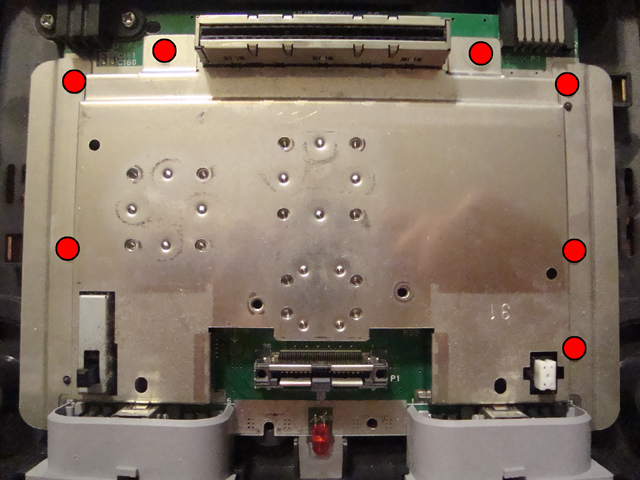
The first step is to take your N64, remove the jumper/expansion pak and flip it upside down, so the screws can be accessed. The screws are shown in red in the picture. Don't forget to take off the black caps, only screws hold them on.
After the screws and caps are gone, flip the N64 over again, then take the top half of the shell off. You should now see the inside of the N64, with all the RF shields and heat sinks. The screws needed to be removed at this point are shown in the picture below.
After those particular screws are gone, slide the big metal "fin" off. Your N64 should now look like the picture below. Remove these next three screws:
Once those are removed, pull off the RF shields shown below. They can be a little tough to get off at first, but they mostly just squeeze into place. They go back in very specific positions and it's easy to forget. The pictures below show the way they go back in.
After those are out of the way, your N64 should look like the following picture. All that's left is to remove are the seven (7) highlighted screws. The two near the cart slot are longer than the others, keep that in mind.
The RF shield/heat sink comes off relatively easy, just put it in a safe spot. Now your N64 should look like the below picture.
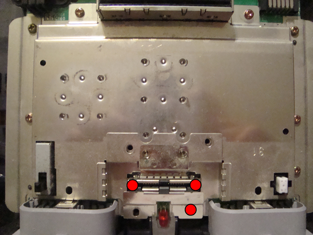
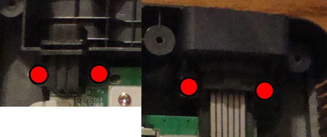
Before we get to the soldering part of this guide, we should really get the switches out of the way first, which involves drilling holes. First thing to do is remove the screws holding the power jack and AV port in place, those are shown in the picture below. Once those are off, the N64 motherboard comes out pretty easily, don't forget to hold onto the bottom RF shield.
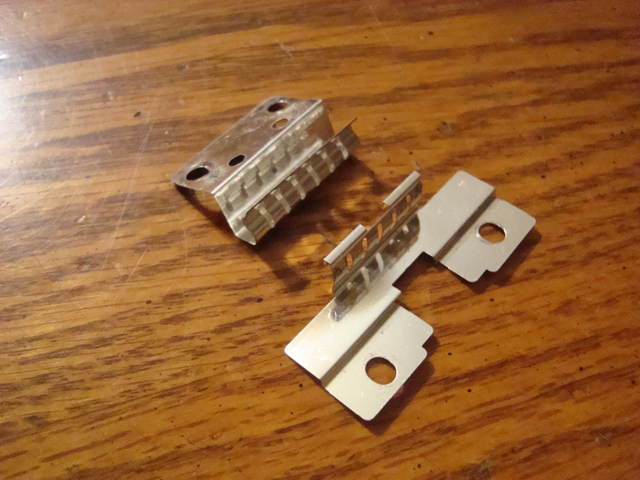
After that, there's a couple of metal screw plates and an LED light softener, those will fall out if you flip the N64 shell upside down, so they have to be taken out and put in a safe place.
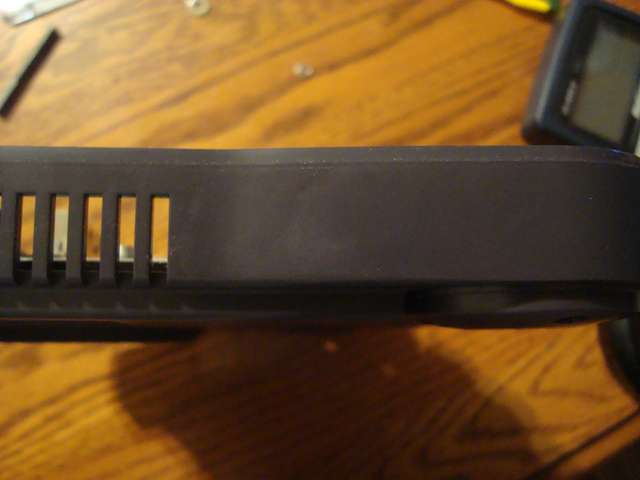
The next obstacle is deciding on a place to put the switches. Most overclock guides online don't offer switch placement suggestions. This guide however, does. I for one spent a long time studying the shell of the N64, looking for a decent place to put the switches. The front wasn't good, not enough room for two of them. The top isn't that great either, it's beauty shouldn't be tampered with. Eventually I decided upon the location shown in the picture below. It's on the left side of the N64, on the bottom shell. Why here in particular? Because the panel here is safe from plastic supports inside the N64, and it's on the bottom shell, so the top can always be removed without fear of wrecking the wires.
For just two holes, I didn't need to use a drilling guide, but you may need to. Just take some masking tape, a ruler and a pen or sharpie, and just mark out where you want your holes to be, by marking the edges of the tape, drawing lines and dotting where the holes go. If you know how to use a ruler, this shouldn't be hard.
When drilling the holes, go slowly so you don't drill the holes too big. Keep your switches on hand so you know when the holes are just big enough, or if they need to be a bit bigger. Also, watch out for any plastic supports, it's really difficult to clear them away cleanly if you happen to drill into one.
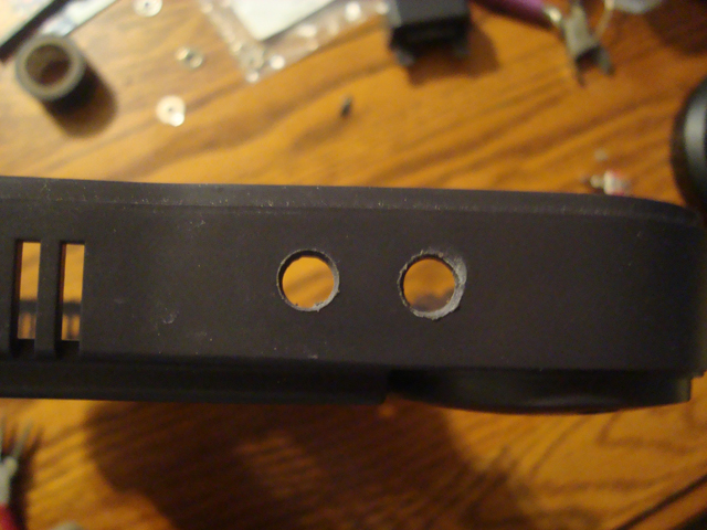
And in no time at all, there's two holes. The one on the right got effed up a bit because some plastic built up on my dremel bit and rubbed off a bit too much of the surface. It's not really that big of a problem though. Now that we have our holes drilled out, we can focus on the soldering part of the guide. You can leave the motherboard out to do this, or just leave it in the bottom shell. If you go with the latter, just follow this guide in reverse, but be mindful of the AV port cover, it has to go on at the same time as the motherboard.
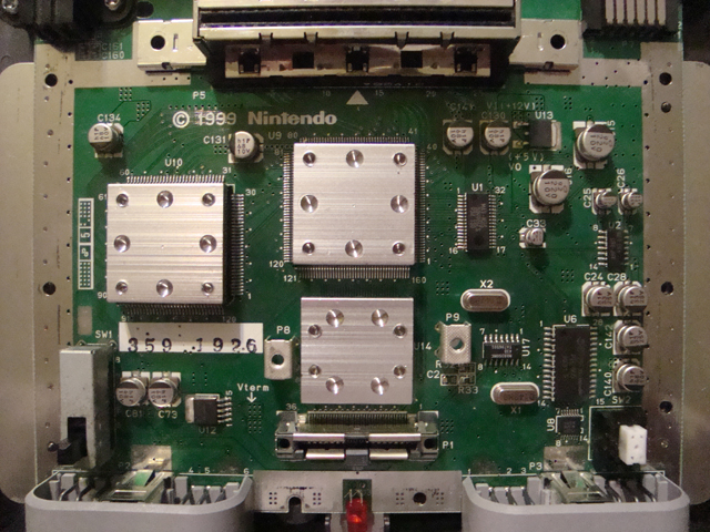
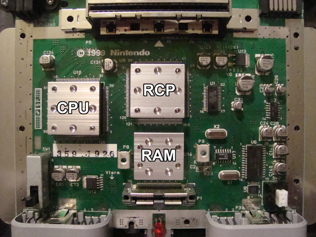
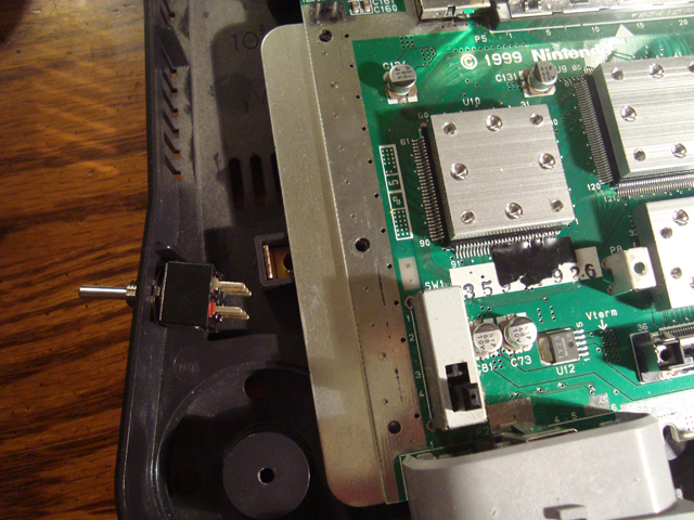
Now, this is what the motherboard should look like for the next steps. The CPU is on the left, as shown in the pic.
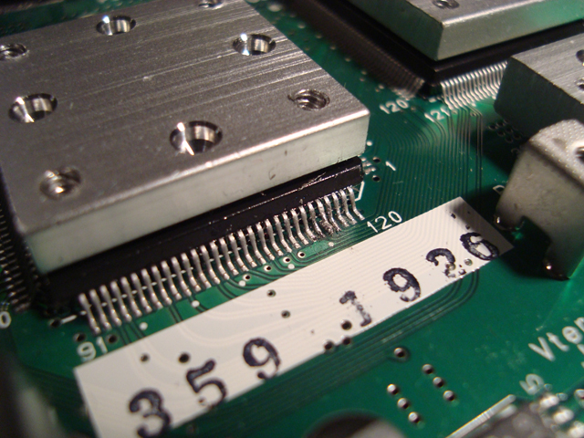
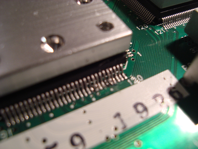
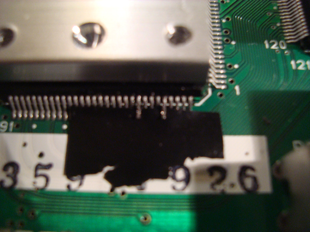
Below shows exactly where we'll be working.
WARNING: From here on, we'll not only be using the soldering iron, but due to the design of the N64's motherboard, we have no choice but to lift the two pins needed for this mod. No matter the type of chip, doing this poses a severe risk of damaging the leg. In the case of the N64 CPU, which has very small legs, they are very delicate and will break if you aren't careful, or if you bend too hard, or if it isn't hot enough yet. Micro-64 takes no responsibility if you break your N64 during this section of the guide.
Now, how do you lift up a leg on a chip? In theory, it's not that hard, it's just incredibly easy to screw up. What you do is heat the base of the leg, but not push against it with the soldering iron. While doing this, you fit the blade of the exacto-knife behind the chip, then anchor against the other pins, and carefully push the leg away from the chip. Most likely, the leg won't bend perfectly straight up during this procedure. To fix this, just swap your tools between hands and keep going. You don't have to lift the leg up very far, just enough to clear the board. Do this with both legs, they should look like the pictures below, sorry for the blurriness, the camera didn't want to cooperate.
To protect the other legs of the CPU, it's advised to stick a piece of electrical tape underneath the legs you just lifted up. Just lightly lay the electrical tape down and try to slide it under. Just be careful while you're doing this, those lifted legs are still very fragile. One wrong move and they'll break off.
This is a decent time to mount the switches in the holes we drilled earlier. Toggle switches are pretty self explanatory in how to mount them. I know the example picture below has only one switch shown, but work with me here. Just pretend there's two switches shown.
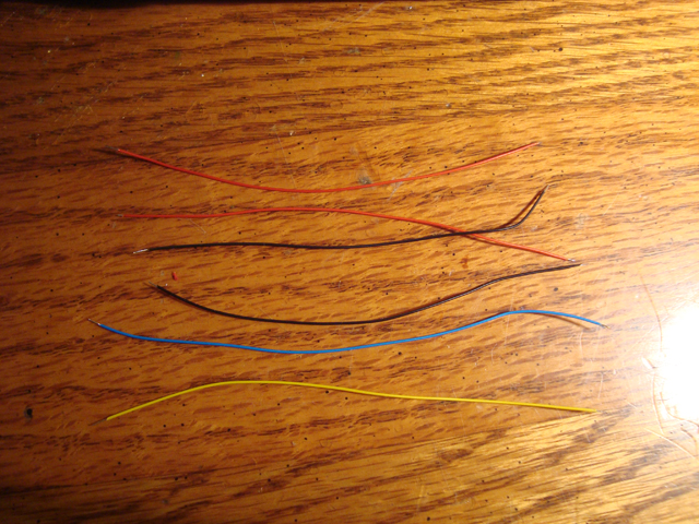
Next, we'll need some wire. There's lots of types to choose from, but I like this kynar wire. It's thin and comes in a range of colors. We need two wires for the two pins we just lifted (blue and yellow), two ground wires (black) and two voltage wires (red). Six in total. They don't have to be a specific length, just reference the distance from the switches to the CPU, or the caps below it, then give yourself some extra wire length just in case. You can always make your wires shorter later, but not longer.
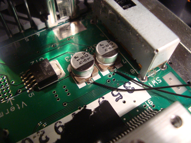
First, let's start with the ground wires. You can take ground from the two caps below the CPU. The black side of the cap indicates the side with ground on it in this case. Other guides recommend using one cap per switch, so we might as well do it here too. I think it's done to avoid impedence issues with the voltage.
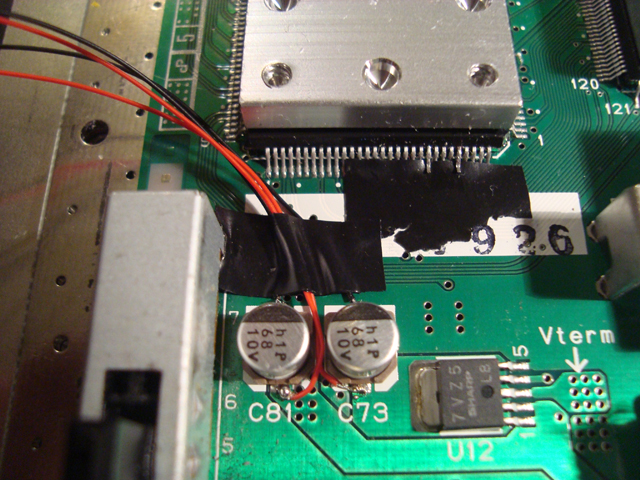
3.3v can be had from the (presumably positive) side of the capacitors. Just solder them as shown below. You can wrap them around like I did. I recommend taping the wires down at this point, also as shown below. You may want to solder the wires of one cap together, so they don't get mixed up later.
Let's solder the wires for the CPU pins next. You can solder which ever color wires to the pins, or do it according to this guide. Don't forget to be careful when soldering to the lifted legs.
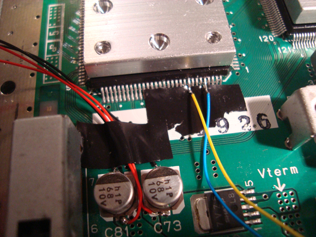
After soldering the CPU wires, carefully bend them so they face left, then tape them down. Your mod so far should look like the below picture. Yes, there's still only one switch, I realize that. This is just another picture I took before realizing this mod was just plain easier with two switches.

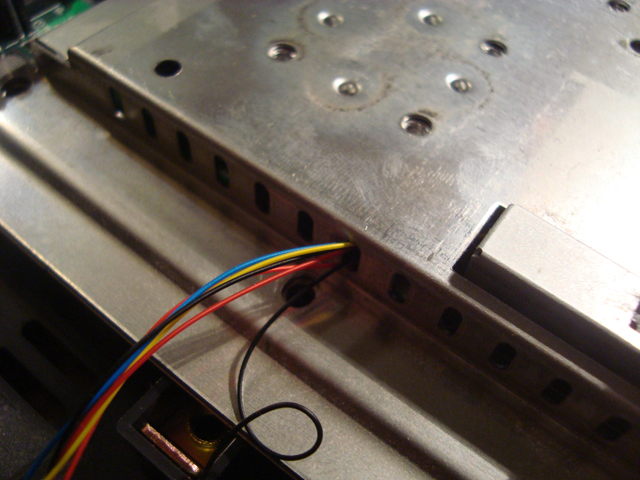
This next part is a bit tricky. Since all the RF shields and heat sinks must be installed for the N64 to disperse heat properly, the wires have to go through the shielding some how. On the left side of the largest RF shield, there's air vents. Depending on the gauge of your wires, they should be able to fit through at least one of the vent holes, as shown below. You may want to put one screw back in to hold the large RF shield/heat sink in place while you finish the mod.
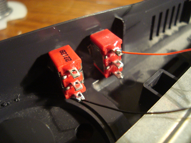
This next part details the connection of the wires to the switches. This guide shows an easy way to configure the switches, so the two common speeds (1.5x and 2.0x) are easily accessible. Take the wires of one capacitor and solder them like this.
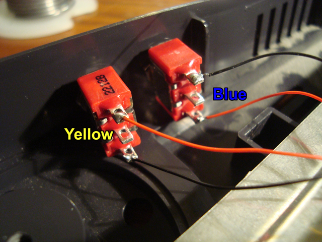
Next, solder the wires of the other capacitor (you may have to desolder the two wires if you tied them together before) to the switches like in the picture below. Then solder the blue (pin 116) wire to the right switch, yellow (pin 112) goes on the left. Sorry I don't have a picture showing this.
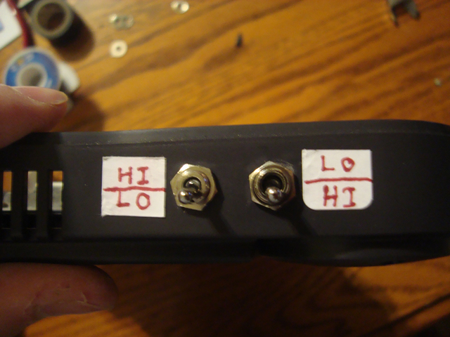
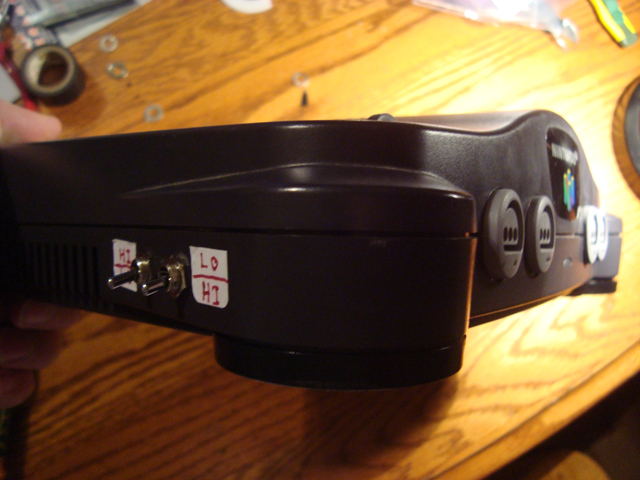
Although at this point, the mod is functionally complete, you might want to add stickers to explain what the switches do. If you're doing this mod according to this guide, you can always copy the labels I made. Since most people don't understand abbreviations like 3.3v and GND, I went with labeling the switch functions with "HI" and "LO", short for high and low, which is basically what voltage and ground are. Due to how we wired the switches, the labels have to be written as shown below:
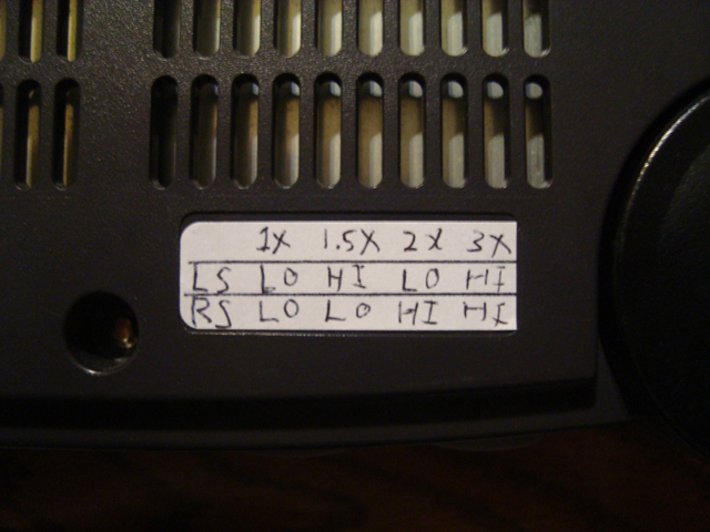
To make things easier for anyone else using the N64, or yourself if you are forgetful, sticking a switch chart to the underside of the N64 is a good idea, like the one shown below. Yeah, I know the writing is a bit sloppy, but it gets the job done. If you notice, 1.5x and 2.0x are set by flipping both switches up and down, which makes things pretty simple.
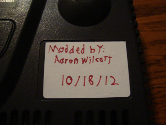
And if you're cool like me, you can use the other label space under the N64 to write your name on and the date when the mod was completed. Thanks for leaving two spots to add labels Nintendo! I know my handwriting sucks, but I'm left handed and write left to right, so I don't normally see the letters I wrote before.
Here's what your N64 might look like when it's done, if you were following this guide. You can put your switches anywhere you want, or wire them to your liking, this guide is just an example, much like the picture below:
There's at least one drawback to this mod however. From what I've tested, no N64 game can start up with the N64's clock multiplier set to 3.0x, so it's a bit useless to add. Also, some games might still feel slow even at 2.0x, this is because the N64's biggest cause of slowdown is the RCP's fill rate. There is no solution to this problem, because the RCP's clock speed is derived from the TV timing.
Other guides suggest installing a fan or two because the N64 can be toasty at 2.0x. I however, haven't noticed any increased heat, certainly not enough to really warrant a fan. If heat is a concern for you, it's not that hard to install a fan, just find a nice place to mount the fan, maybe cut some new grilling in the plastic shell, then either solder the fan's +12v input to a +12v source inside the N64, or use an external power supply.
If you've reached this paragraph with a newly modded N64 in your hands, congrats! Enjoy playing games with less slowdown than before, or in slow motion if you go with the 1.0x speed. Here's a video clip showing what a difference overclocking the N64 can make.
Click here for a video showing the overclock mod in action.
Written by Aaron Wilcott
October 31 2012
|